1. 工具整体思路
mbist流程的整体思路是:
根据第一步的设置创建dft specification,这里面包含了插入电路需要用到的所有信息。
根据创建的dft specification产生并插入指定的电路。
- 产生测试pattern。
2.插入mbist具体流程
2.1提前准备的文件
RTL或者gate-level的netlist:需要插入mbist 的design
能被tessent识别的Memory BIST libraries:描述memory的端口信息和使用的算法,
能被Tessent识别的 cell library:design中存在standard cell时,工具使用对应的cell library来link standard cell
verilog model:memory的verilog模型
2.2 TESSENT MBIST INSERT FOLW
insert memory bist的思路是首先生成dft_specification,然后工具根据dft specification生成并插入测试逻辑。
具体如下:
- 脚本执行:
tessent –shell -64 –log mbist.log –replace –dofile mbist_insert.do
Do文件解析
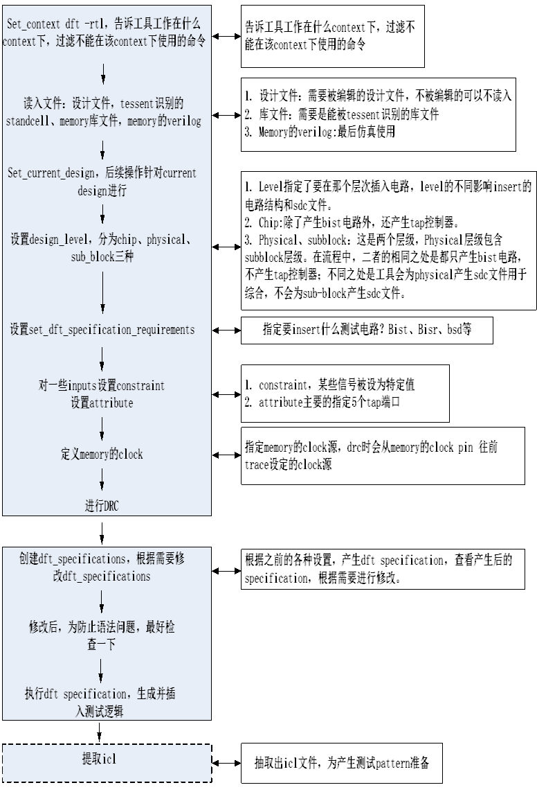
- 设置context
在RTL level插入mbist时,需要将context设置为dft,指示工具对设计文件做修改,加上rtl选项,指示在RTL level进行修改。
命令:Set_context dft -rtl
- 加载设计文件以及库文件
需要明确读入的设计文件应该包含:
例化了memory的module、memory的verilog module、memory的clock路径经过的module、例化mbist控制器的module(为mbist提供插入位置)、mbist信号穿过的module。对于不需要明确读入的module,应该把它们设置成black box或者读入它们的仿真model。
命令:read_verilog *.v
需要读入的库文件有两种:
这里的库文件是Tessent cell library,它里面包含了cell的功能信息和insertion attribute。其中功能信息可以被Tessent用来仿真,insertion attributes可以用于测试逻辑的插入。在RTL level,用到的library是PAD library,告诉工具哪些cell是PAD以及这个PAD的功能。工具在插入电路时将内部信号接到PAD 合适的pin上面。类似于synopsys的lib文件。
命令:read_cell_library *
memory的TCDs(Tessent core descriptions)。这是memory的端口描述,用来告诉工具各个port的宽度和用途等信息,类似于mbistarchitect中的memory model
命令read_core_descriptions *
- 设置current design和design level
Set_current_design设置design的top level,后续的命令作用于这个level
Set_design_level设置current design的level,chip、physical_block或者sub_block。告诉工具这个design是处于chip level还是physical_level、sub_level。
Physical level和sublevel是芯片内部的层次,physicallevel的范围比sublevel的范围更大,即sublevel是physicallevel的子集。这二者造成的影响是工具会为physicallevel产生对应的sdc,不会为sublevel产生。
- 设置dft_specification_resuirements,告诉工具需要插入mbist
如果要插入memory bist,那么需要用命令set_dft_specification_requirements告诉工具。
- 添加约束
这些约束在后续步骤中会体现在dft specification中。常见的命令有
set_attribute_value和set_config_value。
set_attribute_value用来设置object的某个attribute的值;插入tap controller时,需要用这个命令设置tap 的5个PAD;
例子,设置TCK
set_attribute_value PAD_35 –name function –value TCK
set_config_value用来设置dft specification中某个object的值。
- 指定memory的clock
使用add_clocks定义出clock的source,工具会从memory的clock pin trace,直到定义的clocksource,如果trace不到clock source,那么工具报错,所以必须定义clock。
- 进行DRC
确保通过之前的设置,当前设计已经满足插入mbist的规则
使用命令check_design_rule
- 生成dft specification
这个文件是根据4、5、6步骤中的设置产生的。其中的内容引导工具生成并插入需要的测试逻辑,包括ijtag网络、memory bist controller;需要查看里面的内容时,可以写到文件中或者report到屏幕上。
使用create_dft_specification可以创建default DFT specification。创建的DFT specification存在于内存中。
可以使用report_config_data来报出DFT specification。
总的来说,DFT Specification告诉工具要插入什么电路,以及插入时用到其他的信息。
检查第8步生成的dft specification,如果不符合期望,就进行修改;
生成default configuration后,如果需要修改,可以使用三种方法修改:
回到setup mode,修改constraint,重新生成DFT specification
使用GUI来编辑DFT specification
在内存中修改DFT specification,推荐使用这种方法,因为编辑命令可以写在脚本中,能重复使用。
例子:在内存中使用命令修改
Dft specification 中包含memory bist controller的clock,需要改变时,可以使用命令set_config_value 来修改
- 编辑dft specification后,推荐核实一下编辑后的dft specification没有错误;
命令process_dft_specification –validate_only
- 根据第9步的dft specification,工具生成并插入需要的测试逻辑;
命令process_dft_specification
创建完DFT Specification后,就可以生成并且插入所有在DFT specification中要求的DFT hardware。对于Tessent MemoryBIST,在chip level插入时,TAP controller被插入;在physical 或者sub-block level插入时,IJTAG host scan interface被插入。
命令是process_dft_specification
- 提取ICL网络,后续用于产生测试pattern;
使用命令extract_icl核实插入的ICL modules之间的连接性是否合适,如果没有DRC violation,提取出top-level的ICL描述。ICL描述了ijtag网络的连接关系,被用来产生pattern。这个命令也创建SDC file,可以用于综合。
对插入了mbist的设计产生测试pattern
3.产生测试pattern的流程
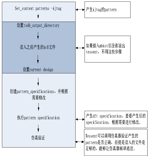
设置context,告诉工具需要工作在什么context下,dft或者pattern;
产生测试pattern,需要设置context为patterns,加上ijtag选项表示产生的是给ijtag网络使用的 pattern
命令:set_context patterns -ijtag
读入之前生成的icl文件;
将之前产生的icl读入
命令:read_icl *.icl
设置current design;
使用命令set_current_design设置
生成pattern specification。这个文件引导工具产生测试向量;
Pattern类型有两类,仿真使用和测试使用的。使用create_patterns_specificaton命令产生pattern specification,它存在于内存中。需要查看时可以用reprot_config_data将其报告到屏幕上。
检查第4步生成的pattern specification,如果不符合期望,就进行修改;
通常情况下不需要修改default pattern specification,因为default specification会测量所有插入的test logic,通常是IJTAG 网络、以及所有相关的instruments。测试相关的pattern可以根据需要通过修改来产生。修改的方法有3中。
- 在内存中编辑,推荐这种方法,因为在内存中编辑是使用tcl或者dofile,可以形成脚本,重复使用。
例子,将测试周期修改为50ns
set pat_spec [create_patterns_specification]
set_config_value –in $pat_spec/Patterns(MemoryBist_P1)/tester_period 50ns
将pattern specification写出到文件中,编辑后读回。
在GUI中编辑pattern specification
- 工具根据pattern specification产生测试向量
根据第4步产生的pattern specification,使用命令process_patterns_specification可以产生patterns和testbench。


网友留言: